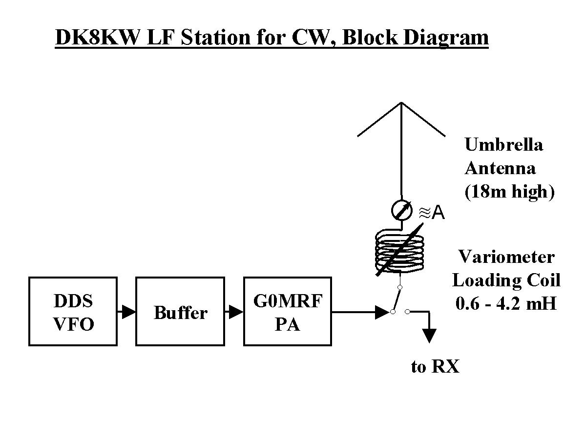
| Transmitter | DDS VFO II (click here for details) made by S&S
Engineering. This VFO has a resolution of 1 Hz and an accuracy in the
same range. This DDS VFO type II is a real "overkill" for longwave, as
it goes from 0 Hz to 60 MHz. The VFO has an output of about 0.6 Volts p/p
at 50 Ohms.
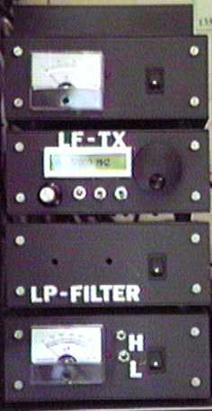
Top to bottom: PA, TX, Low-Pass Filter,
|
| The TX contains a 2-stage buffer using one MAV 3 and one single IRFP
450 to get about 1 watt output, resulting in an ERP (according to CCIR
curves) of 100 mW.
|
|
| PA | G0MRF
PA with 4 x IRFP 450, now running at full power (approx. 380 W input/280
W output)
|
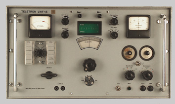
| Pre-Selector | I use the pre-selector section of a Teletron LWF45.
|
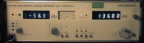
| Receiver | MV 62 Selective Level Meter as front-end and
converter, 1.7 or 0.1 kHz bandwidth, output IF on 200 kHz
|
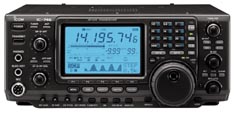
| IC-746 as IF receiver on 200 kHz, equipped with cascaded 250 Hz and
500 Hz CW filter (plus DSP filter, if needed)
|
|
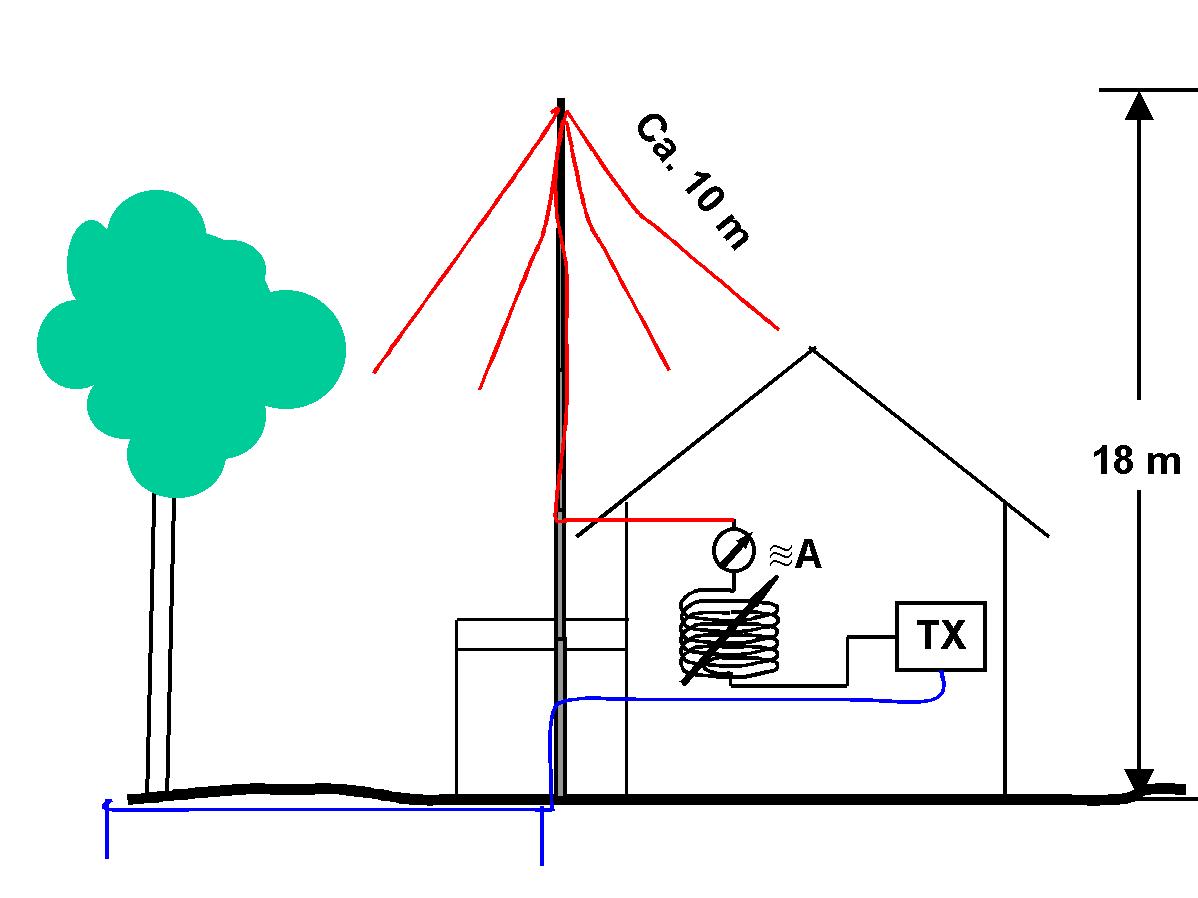
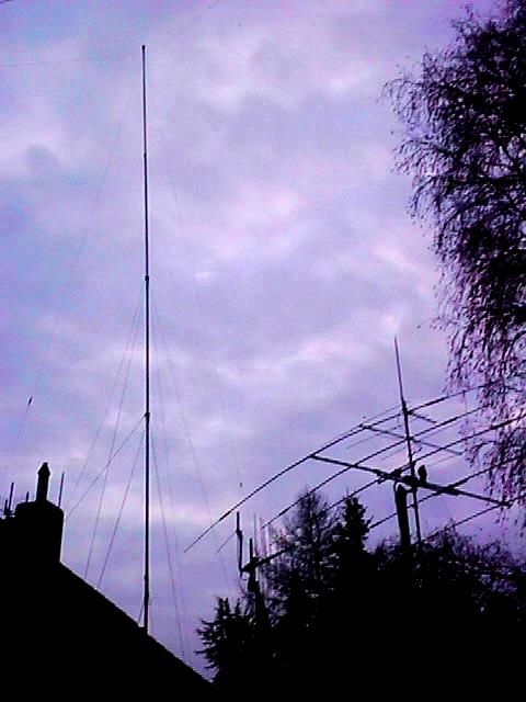
| Antenna | New setup: My new antenna is a simplified version of what is called
in broadcast engineering an "Umbrella-Antenna". It consists of a 18m vertical
telescopic fibre glas mast (height depends on the wind condictions), four
top-load wires, each about 15 to 20m long at a relatively steep angle (still
leaving some room for improvement).
I use this antenna for transmitting and receiving, the signal strength of DCF39 has improved from -46 dB(75) to -23 dB(75) compared to my previous antenna.
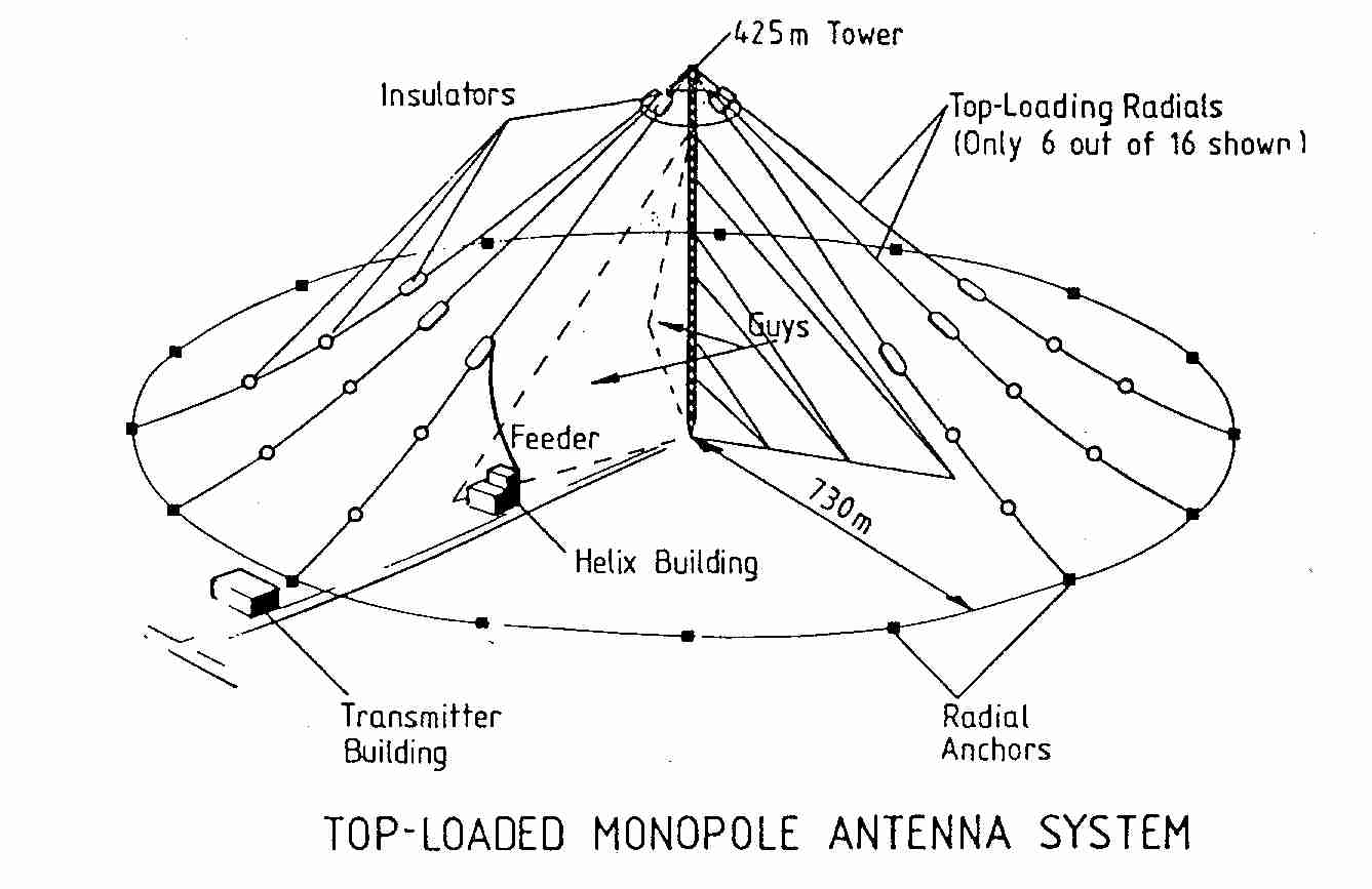
The picture below shows a commercial umbrella-antenna, also called top-loaded monopole antenna, build for a frequency in the 12 kHz range for the former Omega Navigation system. According to Klawitter and Herold, those antennas had 16 top-load and 16 buried radials. The 425m (!) high tower would roughly compare to a 42m high umbrella-antenna for 136 kHz.
Previously I used a Marconi type T-antenna, consisting of a 82m long
windom antenna for 160 m, u-shaped in a height of 8 to 12 m, soald and
shield of coaxial cable connected in my shack. I was copied in the U.K.
by G3XDV (707 km) with this relatively simple antenna setup and had a succesful
2-way QSO with HB9ASB (645 km)!
|
| Antenna Current Meter | Russian-type antenna current meter (0-3 A, 50 Hz-7.5 MHz)
|
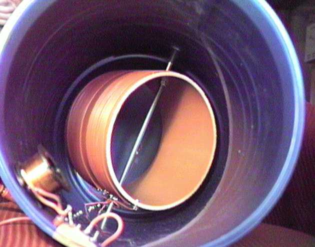
| Loading Coil | Primary 3.4 mH loading coild 1/3 way up the antenna. This coil improved
my ERP signal about 4-5 dB.
Additional variometer loading coil in my shack, wound approx. 130 m of 0.2 mm Litz wire on 27 cm diameter, 40 cm height plastic bin 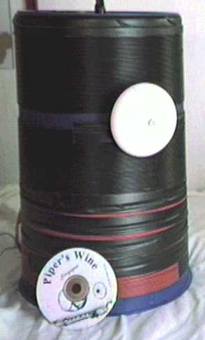
The Piper's
Wine-CD gives you an idea
|
| Antenna Switch |
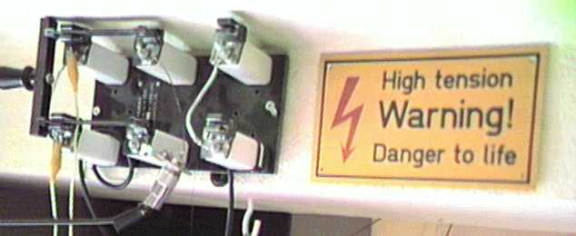
Be careful: High Voltage! I used this antenna switch to switch between longwave and 160/80/40m, as I used the same antenna for all those bands. This explains, why I needed a coule of seconds between transmit and receive when I run crossband QSOs! With the new seperate LF antenna, this should be easier now! I use this monster switch now to ground the umbrella-antenna. |
| Ground System | One main ground rod about 3 m deep, plus central heating and water pipe system in my old farm house connected, another 2.4m long ground rod at the end of a 20m long buried radial, still two or three more ground radials planned. |
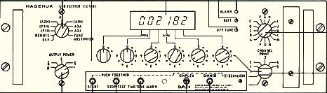
| Linear Modes (PSK31, HELL, etc) | Since December 2000 I have got a Hagenuk EX 1001 SSB Exciter with LSB/USB
option. Late Peter, DJ8WL had told me about this device which produces
CW and SSB signals between 100 kHz and 30 MHz in 100 Hz steps.
I use a small buffer amplifier (developed by OM2TW) to increase the signal level from about 20 mW to 4 Watts, sufficient power to drive the G0MRF-PA. With this setup I am occasionally QRV on 137.500 kHz in PSK31 or 137.400
in HELL and other experimental modes.
|