 This strong
signal can be heard throughout Europe. The Mark frequency of 138.830 kHz
can be used very nicely as a frequency alignment indicator. The modulation
switches over to the space freqeuncy every 10 seconds or so.
This strong
signal can be heard throughout Europe. The Mark frequency of 138.830 kHz
can be used very nicely as a frequency alignment indicator. The modulation
switches over to the space freqeuncy every 10 seconds or so.
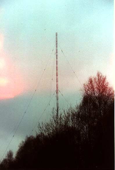
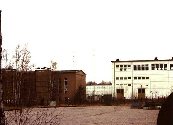
DCF39 on (nominal) 139.000 kHz, QTH near Magdeburg/Germany
This strong
signal can be heard throughout Europe. The Mark frequency of 138.830 kHz
can be used very nicely as a frequency alignment indicator. The modulation
switches over to the space freqeuncy every 10 seconds or so.
There is strong evidence that this signal was copied in Australia using a very long integration method based on DSP harware.
Signal strength: constant -46 dBu (at 75 Ohm) at my old Marconi t-antenna, -23 dBu (75) with the new vertical antenna.
(special thanks to Gamal for the following infomation)
More information can be found at http://www.funkrundsteuerung.de/index.html.![]()
==========================================
Station DCF39
purpose remote control service
==========================================
nominal frequency 139.000 kHz
modulation: ASCII (8E1) 200 baud FSK 340Hz shift
mark_frequency 138.830 kHz
space_frequency 139.170 kHz
-------------------------------------------
from topographic map 50
latitude 52d17m18s N
longitude 11d53m51s E
locator JO52WG
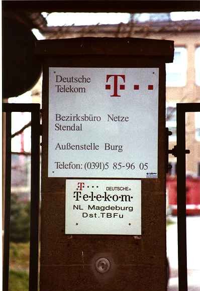
located at Burg near Magdeburg
--------------------------------------------
user:
EFR - Europaeische Funk-Rundsteuerung GmbH
Nymphenburger Str. 39
80335 München
Germany
+49-891254-4681 phone
+49-891254-4682 fax
e-mail
info@efr.de
--------------------------------------------
operator:
Deutsche Telekom AG
Want to ask them to turn their antenna to your
direction? Here is their telephone number!
--------------------------------------------
transmitter power 50 kW
vertical monopole antenna 324m high
EIRP about 40 kW (omnidirectional),
confirmed by Gamal's and my
measurements taken on April 8, 2000
--------------------------------------------
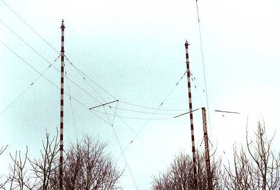
There are 5 (were 6) antennas on this site:
(1) 210m vertical monopole
52d17m21s north
11d54m29s east
This is a guyed isolated tubular mast
used for BC transmissions of
"Radioropa Info" on 261kHz
powered by a Tesla Transmitter
which is designed for nominal 200kW
but presently operated with 50kW HFout
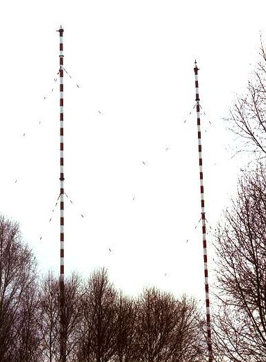
(2) 210m vertical monopole
This is a guyed isolated tubular mast
presently unused
formerly used for MW transmissions
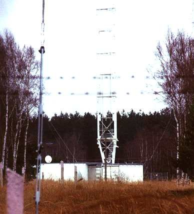
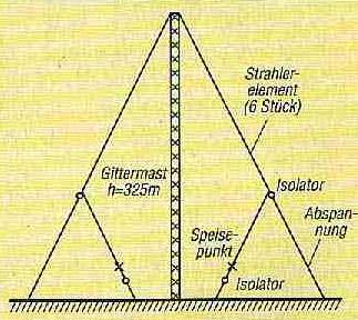
(3) 324m vertical biconical antenna
52d17m18s north
11d53m51s east
This is a hexafilar wire antenna
supported by fabric mast
used for transmissions of DCF39
powered by
Telefunken Transmitter
which is a MOSFET amp providing
50kW HFout
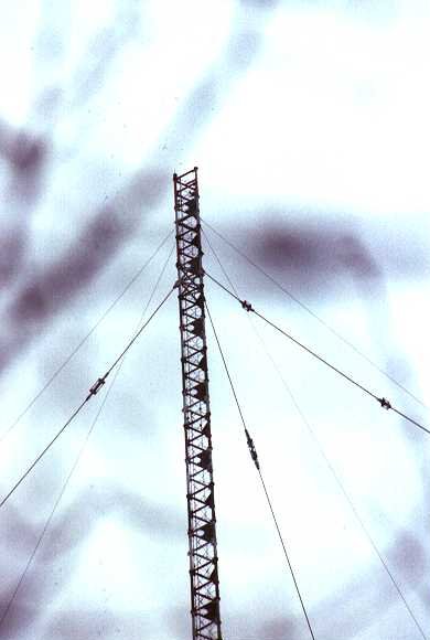
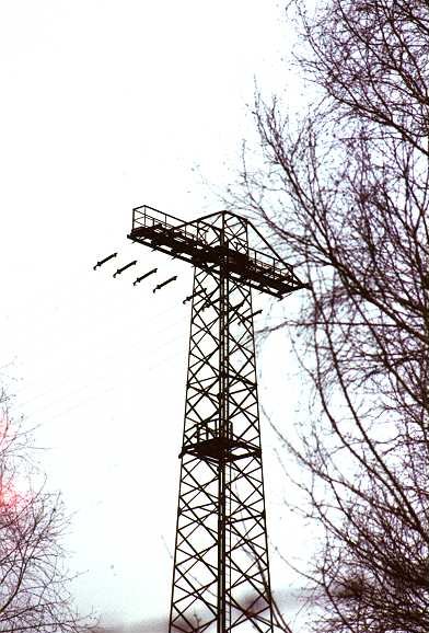
Top and ...
... bottom of the DCF39 mast
(4) triple, 70m octofilar horizontal dipole
presently unused
formerly used for MW transmissions
(1575kHz Radio Berlin International)
(5) 55m trideco antenna
> presently unused
> formerly used for MW transmissions as backup antenna
NONEXISTENT - scrapped !!!
(6) 55m trideco antenna
presently unused
formerly used for MW transmissions as backup antenna
a
a N
(5) A
a | 52N17
a W--+--E 11E54
a | JO52WG
a S
(2)O
a
========= (1)O
a (4) =========
a
=========
a (3) O
a
(6) A
--------------------------------------------
The frequency was formerly (<1995) allocated
to DCF39, a transmitter located in Bad Vilbel
(north of Frankfurt/Main).
==========================================
Transmissions are used for power-line and power-plant related remote
control. More information (in German language) can be found at the homepage
www.efr.de.
More information on DCF39:
I have digged in my files and found some interesting
information compiled
by Tom, DL8AAM a while ago, that he posted on
the packet radio network. It
should even be possible to decode the signal.
The callsign that Tom states (DCF49) probably
is only valid for the 129.1
kHz transmitter, same is tru for the power (Gamal
had posted some technical
information on the transmitter in Burg, DCF39,
here a while ago). There is
even some uncertainty about the callsign within
the company running it, I
have heard people saying that they received "DBF39"
as well as "DCF39" in
ASCII.
Best 73
Geri, DK8KW (W1KW)
http://www.qru.de
------------------------------------------------------------------
VLF @EU
de:DL8AAM 12.01.98 16:00 360 6803 Bytes
DCF49 on 139 kHz
*** Bulletin-ID: 121803DB0NDR ***
980112/1603z DB0ABZ, 980112/1600z DB0ERF, 980112/1557z
DB0MAK
980112/1457z OK0PKL, 980112/1611z DB0DLN, 980112/1538Z
DB0TUD
980112/1530z DB0NDR
de DL8AAM @ DB0NDR.#NDS.DEU.EU (Tom)
to VLF @ EU
*!* HOT NEWS *!*
EFR - Europaeische Funk-Rundsteuerung GmbH
-----------------------------------------
Many European dxers have logged DCF49 on 129.1
kHz. The station is
still listed by some publishers as 'BMPT, Bonn',
but that is not correct.
So, if it isn't BMPT Bonn, then who is responsible
for the transmissions?
this month I have the true story for you.
Remember where you read it first.......
YES, in the WUN newsletter!!!
My sincere thanks to Klaus Betke for his research
and to EFR Berlin
for their help and information.
Station
: EFR Berlin
Callsign
: DCF49
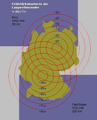
Transmission site: LW-facility Mainflingen
Radiated Power : 60 kW
Frequencies
: 129.1 and 139.0 kHz
Transmission mode: 200 bps ASCII
Modulation
: FSK
Control protocol : DIN 19244
Message format : FT 1.2
Service
: Long wave Teleswitching
Long wave teleswitching is a new way in load management
technology. It
replaces the well adapted ripple-control technology,
which is widely
used in the utility industry worldwide.
First a few words about ripple control. It is
used for tariff-switching
applications and load management as well as for
the control of street
lighting for example. Basically, ripple control
systems are used to
spread information to lots of receivers installed
in the supply region
of a utility. Today, ripple control is not considered
to be a very
economical method but, for that, a relatively
safe method.
Ripple control systems use the existing mains
as signal carrier (i.e.
energy suppliers transmit 'tones' over the power
lines for this purpose).
since the mains network is designed for 50 Hz,
a ripple control freq of
a 100 Hz is being affected under certain circumstances.
Consequently
the conventional ripple control will face changes
due to new transmis-
sion methods and additional intelligence in modern
receivers. The newly
offered long wave teleswitching system is using
a radio channel to
transmit the information via air, apart from
that it follows the same
basic principles known from conventional ripple
control.
The economical management of modern power supply
systems requires possi-
bilities to transmit commands to control the
consumption of electricity
at any time. Audio frequency ripple control systems
have been used for
many years. They help to transmit control commands
from the control
centre of an utility via the mains which can
be received at any point of
the network. Many utilities are already using
these systems (some 410
companies in Germany alone).
The main LW Teleswitching system components are:
- control centre
- central computer
- LW teleswitch transmitter
- LW teleswitch receiver
The CONTROL CENTRE of the utility consists of
a standard computer
system (PC). The program used, enables every
participant to initiate
his own messages. A reference-receiver signalises
back the messages
sent by radio for monitoring purposes.
The CENTRAL COMPUTER is located in Mainflingen.
This computer serves
to assign priorities, buffer, manage and pass
on messages to the trans-
mitter.
The LW TELESWITCH RECEIVER is based on existing
conventional ripple
control technology. The network filter has been
replaced by a RF (radio
freq) filter. The areal is fixed on the receiver
but can also be in-
stalled separately, if the location poses problems.
The receiver has a
program memory to store repetitive control functions.
This means that
only program changes have to be transmitted.
The LW TRANSMITTER operates at carrier freqs
of 129.1 and 139.0 kHz.
modulation is by FSK; keying is done by shifting
between a freq above
and below the carrier freq.
CONTROL TASKS. Modern LW teleswitch can fulfill
the same tasks as
conventional ripple control. For example,
- switching tasks, such as:
o rate switching of multi tariff meters
(night and day rates)
o switching of streetlights
o switching of water heaters (to cause
heaters to use the night charge)
load control tasks, such as:
o group heating control depending on the
weather
o load decrease
o influence of load variation in industrial
companies etc.
o blocking of heat pump systems
- special tasks, such as:
o transmission of tariff information remote
parameter assignment of
receiver groups or individual receivers.
o TELEGRAM FORMAT
most telegrams are a few bytes long i.e. about
1 second), but a length
of up to 30 bytes will be possible soon. Reaction
time is a few seconds.
Each telegram is transmitted asynchronous at
200 Baud and 340 Hz shift,
using 8 data bits plus even parity bit. The format
is derived from the
international standard IEC 60870-5, or 870-5
in the old numbering system.
It consists of 7 header bytes, a user data field
of up to 16 bytes, and
trailing bytes:
- Start 68h (h = hexadecimal)
- L field
- L field
- Start
68h
- C field
- A field
- CI field
- User data
0-16 bytes
- Check sum
- Stop
16h
After the start character 68h, the length field
(L field) is transmitted
twice, followed by the start character once again.
This is followed by
the C field, the A field and the CI field. The
L field gives the number
of user data bytes plus 3 (for C, A, CI).
The C field (control field, function field) specifies
the direction of
data flow and is responsible for various additional
tasks. The A field
address field) serves to address the receiver;
adresses 1 through 250
can be allocated to individual parties. Address
255 (FFh) is used to
transmit information to all participants (broadcast).
The meaning of the
CI field (control information field) is not clear.
Maybe it is used as
an address extension. Most often, however, it
is identical to the A field.
The user data field is followed by the check
sum, which is the least
significant byte of the arithmetical sum of C,
A, CI and the user bytes.
Finally the stop character 16h is transmitted.
Most telegrams are sent twice. Currently the
lengths range from L = 5
to L = 13. Occasionally the string "DCF49 TEST"
is transmitted in the
user data field, with L = 13, C = FFh, A = FFh
(broadcast), CI = FFh.
------------------------------------------------------------------
"David L. Wilson" wrote:
> The callsign depends on which transmit site
is actually being used:
> ITU:
> FREQUENCY ³ CNT
³ STATION NAME ³
ADM ³ GEO. COORDINATES ³ CL
>
> 00139.00000K ³ D ³
BURG 1
³ D ³ 011E5400 52N1700 ³ FX
>
> ASSIGN_ID : 096021507
REGION : 1 EMISS/REC : E RECORD TYPE : A01
>
> 1C :
> 1D :
DATE-MRF-UPD : 19.02.1997
> 2C : 01.12.1996
WIC-NBR/PART : 2266/2
> 3A : DBF39
NOTICE-TYPE : 1A1
> 4C : 011E5400 52N1700
RR NOTIF : RR1214
> 4D :
NOISE-ZONE :
> 4E :
SYNC :
> 4G :
> 6B : CV
> 6C :
> 9E(S):
> 10A:
> 12A: 001
> 12B: A
> 13C:
>
>
> FREQUENCY ³ CNT ³
STATION NAME ³ ADM ³
GEO. COORDINATES ³ CL
>
> 00139.00000K ³ D ³
MAINFLINGEN ³
D ³ 009E0000 50N0100 ³ FX
>
> ASSIGN_ID : 080002113
REGION : 1 EMISS/REC : E RECORD TYPE : A01
>
> 1C :
> 1D :
DATE-MRF-UPD : 15.06.1994
> 2C : 10.01.1961
WIC-NBR/PART : 1792/A
> 3A : DCF39
NOTICE-TYPE : 1A1
> 4C : 009E0000 50N0100
RR NOTIF : RR1214
> 4D :
NOISE-ZONE :
> 4E :
SYNC :
> 4G :
> 6B : CR
> 6C :
> 9E(S):
> 10A:
> 12A: 001
> 12B: A
> 13C:
Vaino, OH2LX pcarried out interesting long-term field strength measurements on DCF39.

copyright (c) 2001-2006 by dk8kw, all rights reversed